PLEASE BE ADVISED THAT WE ARE CURRENTLY EXPERIENCING ISSUES WITH OUR INCOMING TELEPHONE SYSTEM.
IF YOU ARE UNABLE TO REACH US BY TELEPHONE, PLEASE USE THE EMAIL ADDRESSES ON THE CONTACT PAGE OR FILL IN THE CONTACT FORM AND ONE OF OUR TEAM MEMBERS WILL GET BACK TO YOU.
Products
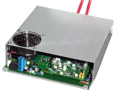
XF Series
25kV to 50kV 100W X-Ray Power Supplies with Floating Heater
XF025, XF030, XF040, XF050
Application: X-Ray Tubes and Electron Guns
- -25kV, -30kV, -40kV or -50kV at 2 mA
- Heater isolated to 50kV 5V at 3 Amp
- Short circuit and flashover proof
- High efficiency, 24 hour burn in
- Safety assessed to EN61010-1
- Beam Current Control, stabilised by heater current.
- Controlled turn-on. Minimises turn-on stress to tube and filament.
- Stand-by Heater Current:, set by Internal potentiometer. 0-100%
- Maximum Heater Current, set by internal potentiometer. 0-100%
The XF series is based on the HW50/2N. It includes an isolated filament supply whose power is controlled to stabilise the beam current and is intended to operated an X-ray tube in the grounded anode mode (filament floating) at up to 50 kV 2 mA. Control of the output voltage & current is by internal potentiometers or by external 10 volt analogue control voltages. All units are short circuit proof and use high frequency pulse width modulated switching techniques, in conjunction with a ferrite step-up transformer to control the output voltage.
Please contact the factory for special versions of this power supply.
| Electrical Specification | |||||||
|---|---|---|---|---|---|---|---|
| Unit Type | MCP Output | Scintillator Output | Isolation | Output Ripple | Inhected Ripple | Size (mm) | Weight (kg) |
| HFD005PAA2.5 | 112V to 1.25kV At 100μA |
MCP Volts x4.5 Clamped @ 4.75kV |
±2.5kV | MCP <150mV pk to pk SCINT <500mV pk to pk |
<50mV (pk-pk) | 185 x 120 x 60 | 1.5 |
| HFD005PAA005 | 112V to 1.25kV At 100μA |
MCP Volts x4.5 Clamped @ 4.75kV |
±5kV | MCP <150mV pk to pk SCINT <500mV pk to pk |
<50mV (pk-pk) | 185 x 120 x 60 | 1.5 |
| HFD005PAA010 | 112V to 1.25kV At 100μA |
MCP Volts x4.5 Clamped @ 4.75kV |
±10kV | MCP <150mV pk to pk SCINT <500mV pk to pk |
<50mV (pk-pk) | 185 x 120 x 60 | 1.5 |
| 1) ripple injected into the power supply providing the floating voltage, measured assuming load capacitance of 1000 pF. | |||||||
The critical MCP voltage, for setting the gain of the detector, is directly controlled by the 10V control input. The Scintillator voltage is X4 the MCP volts, on top of the MCP voltage, so with an MCP voltage of 1kV the Scintillator will be at 4kV (i.e. 4kV above the MCP voltage.) We manufacture a large number of these supplies, customised for different detector characteristics. The ratio of MCP voltage to Scintillator Voltage, and final Scintillator clamping voltage and Zout can readily be customised for your specific detector application. Please consult the factory with your details.
| Input | +24V dc ±10% <0.7A. 0V input common to chassis. |
|---|---|
| Control of MCP Output At Ground Potential |
|
| MCP Voltage Monitor | 0V to +10V ±3% for 0% to 100%. (Zout= 10k) |
| MCP Temp Co-efficient | <0.02% / ºC |
| MCP Drift (after 1 hour warm up) | <0.1% per hour |
| SCINT o/p Voltage | MCP X4.5 ±5% clamped at 4.75kV ±15% Clamp Temp co <650ppm/°C |
| Line Regulation | <0.2% for 1V change in input voltage |
| Load Regulation | <0.2% for 25% to 100% MCP voltage Note Scintillator o/p has Zout of 100Mohms |
| Protection (all outputs) | Protected against intermittent arcing and continued short circuit to ground |
| Environmental Specification | |||
|---|---|---|---|
| Temperature, Storage | +10°C to +50°C. | Humidity (RH) <31°C | 80% maximum |
| Temperature, Operating | -35°C to +85°C. | Humidity (RH) >30°C | Decrease linearly to 50°C |
| Altitude, Operating | Up to 2,000m. | Altitude, storage | Up to 18,000m |
| Mechanical Specification | |
|---|---|
| Mountings | 3 off M4 clearance holes—see outline drg |
| Input & Control | Molex 0.2” 12 way connector (24V power, control and monitor are all at Ground potential.) |
| Outputs | By three 0.5m flying screened (shielded) leads type URM43 labelled ‘INPUT’, ‘MCP’, ‘SCINT’ |